
 中国
中国
 India
India
 Việt nam
 Australia
 대한민국
대한민국
 پاکستان
 ประเทศไทย
 Filipino
 Malaysia
 Bangladesh
 Sri Lanka
 Indonesia
 Узбекистан
 Ireland
 Česká republika
 Türkiye
 United Kingdom
 France
 Deutschland
 Nederland
 España
 Sverige
 Italia
 Polska
 Україна
 Português
 България
 Magyarország
 Lietuva
 Ελλάδα
 Suomen tasavalta
 United States
 Canada
 México
 Brasil
 República de Chile
 South Africa
 المملكة العربية السعودية
 الجمهورية اللبنانية
 امارات عربية متحدة
 اليمن
اليمن
 المملكة الأردنّيّة الهاشميّة
 جمهورية مصر العربية
 la République Tunisienne
 Kenya
Kenya
 Tanzania
 Nigeria
 Other Countries and Regions
INTRODUCTION
In the process of PV system installation, there is process that seems simple and is easy to ignore but can easily bring hidden dangers to the safe operation of the system later. The connection and wiring installation of AC and DC connectors.
Connectors are used as the connection and the power transmission between PV modules, combiner boxes, inverters and other solar PV equipment. Incorrect installation can cause product failures and reduce system revenue. In severe cases, it may cause a fire, which could cause huge economic losses and impact to personal safety.
So, what should be considered when selecting and installing AC and DC connectors? Read on to find out more.
PART1
Connector selection
Solis only selects components from world-renowned brands for inverter design and production, and DC connectors are no exception. Solis uses only genuine, original MC4 connectors. These are chosen for their design durability which includes low voltage drop, low contact resistance, low loss, strong current carrying capacity, and IP68 protection level. As shown in the image below, the original MC4 solar PV connector (seen in green) shows no obvious heating point, so it will not cause local temperature rise.
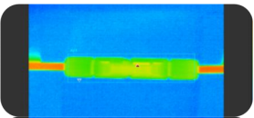
Thermal imaging analysis refers to EN50521 and IEC60512-5-1
Data source: experimental data of connector manufacturers
At the same time, when selecting the wire end connector, it is recommended that customers also use the original MC4 connector to connect to the inverter. The specifications, dimensions and tolerances of connectors from different manufacturers are not consistent, so 100% connection cannot be guaranteed if connectors from different manufacturers are used. If they are forcibly inserted into each other, it can cause problems such as temperature rise, increased contact resistance and the inability to guarantee the IP rating, which will seriously affect the power generation efficiency and safety of the power station.
PART2
Installation specifications and guidance videos for AC and DC connectors
1
DC connector installation specification and instruction video
In a PV power generation system, due to the lack of training of some on-site installation workers and the use of professional installation tools, a series of problems can occur. For the installation details of the DC connector, please refer to the installation manual relating to the product.
① Stripping Specification
Irregular wire stripping, wire core loss, large area wire breakage, and too short stripping will not only lead to increased wire resistance, (resulting in power loss), but also excessive temperature of the connector, which may cause the connector to burn out in severe cases.
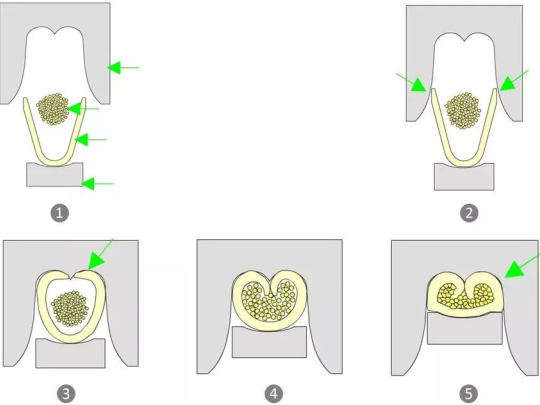
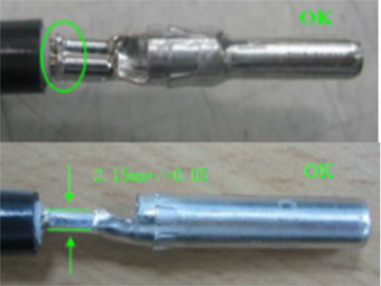
② PIN Crimping Specification
When the PIN needle is crimped, as shown in the figure below, the core riveting part should not be exposed too far to ensure the concentricity of the metal part and the cable is maintained.
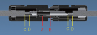
③ PIN Insertion Specification
After the PIN is inserted, the test rod should be used to confirm that the PIN is fully inserted correctly. As shown in the figure, part of the conductor AB is not in contact or contact is insufficient, resulting in an open circuit or virtual connection.This will result in the circuit not working or virtual connection causing burns.
④ Nut Locking Specification
DC connectors in PV systems will be exposed outdoors for a long time so need to be protected. The protection level of conventional DC connectors is generally IP67. The genuine MC4 connector used by Solis is rated higher at IP68. During operation, be sure to lock the nut sufficiently to prevent IP protection failure. Allowing water vapor to penetrate into the connector will cause oxidation, corrosion and accelerated aging of the internal conductor, which will in turncause DC arc burning.
⑤ Plug Operation Specification
The standard installation of DC plugging and doing so unpowered. . Almost all connector installation instructions will clearly state that the connector should not be plugged and unplugged under power. However, there are still live plugging and unplugging conditions on the project site, which can not only cause DC pull but the arc damages the connector and there is then a greater risk of electric shock. When you need to disconnect the connector for on-site maintenance or repair, you must first cut off the power supply and use a clamp-on ammeter to confirm that the current is less than 0.5A.
⑥ Stripping Specification
Before stripping, carefully read the relevant specifications of the installation manual enclosed with the product , Perform the stripping operation according to the recommended stripping length of the inverter to avoid AC connection problems caused by wire stripping.
⑦ Wire Core Plug-in Specification
For plug-in AC connectors, AC cables are usually multi-core cables. Insufficient stripping length and scattered cores are prone to insufficient core insertion. This results in insufficient electrical contact area, leading to increased power loss or abnormal heating causing the connector to burnout.
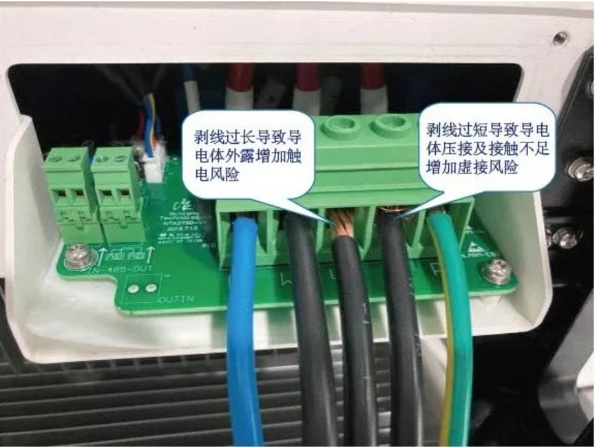
Wiring error case of plug-in AC connector
Excessive stripping leads to conductive body exposure increasing the risk of electric shock.
Too short stripping leads to crimping and insufficient contact of the conductors, increasing the risk of virtual connections
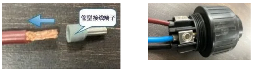
For instances of scattered cores of multi-strand cables, it is recommended to add tube-type terminals to the cores to avoid the scattered cores and achieve complete and reliable connection of AC cable cores and AC connectors.
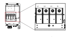
8 Cable crimping specification
If the crimping screw is tightened or the screw's sliding teeth are loose, the joint will be falsely connected. This will increase the contact resistance and cause abnormal heating, which will eventually cause the connector to burn. Therefore, for crimping AC terminals, please refer to the corresponding specifications in the installation manual attached to the product to avoid the above problems.
AC terminal crimp recommendations
PART3
Daily O&M
In order to ensure the reliability of the AC and DC connector wiring and ensure the stable and efficient operation of the system, it is recommended to include the AC and DC connector wiring inspection into the project acceptance project. Perform regular inspections and maintenance after the system has been running for a period of time, and check the AC and DC side wiring for any looseness, abnormality, or improper wiring. A portable thermal imager can be used to detect and compare the operating temperature of the AC and DC connectors to determine whether the wiring is reliable. The temperature rise (test temperature minus the ambient temperature) during the operation of the connector is usually about 10°C. If the temperature rise is too high, there may be abnormal wiring.
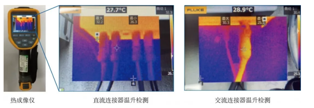
Thermal Imager DC connector temperature rise detection AC connector temperature rise detection
PART4
Summary
For solar PV systems, connectors are small, but they are key components that affect the safe and stable operation of PV power stations. In the early stage of power station construction, the risk of failure caused by connectors is often ignored, but in the later stage, it will become a pain point for power station operation and maintenance.
From the perspective of device selection, this article first recommends the use of genuine MC4 connectors to ensure reliability. Secondly, from the perspective of installation and ongoing operation and maintenance, the AC and DC connector installation specifications and instruction videos should be referred to as well as daily checks as part of regular operation and maintenance of the site.


Få de senaste nyheterna om Ginlong på första gången
Asia/Pacific
Europe
North America
South America
Middle East and Africa
Other Countries and Regions

