Background
The Solis EPM accessory, as an energy control
device, has an enormously powerful function. In addition to controlling
the energy output of the PV system, it can also be used as a reactive
power adjustment and power factor compensation device. During
installation we hear common questions being asked so in
this episode of Solis Seminar we’ve collated the most frequently asked
questions and answered them for you.
Frequently Asked Questions
1) What is the difference between the EPM models available; EPM1-5G, EPM3-5G, EPM3-5G-PLUS?
Answer:
EPM1-5G
This
is suitable for 220V/230V single-phase systems, can be used across
different inverter models, and can control up to 10 inverters.
EPM3-5G
This
is suitable for three-phase, three-wire systems, 220VAC, 380/400VAC,
480VAC voltage, can be used across different inverter models, can
control up to 10 inverters and is suitable for three-phase Delta
grids with no neutral.
EPM3-5G-PLUS
This is suitable for
three-phase, four-wire systems, 220VAC, 380/400VAC voltage, can be used
across different inverter models and the maximum theoretical quantity of
inverters it can control is 80. This does not support grids with
no neutral.
2) Why is the power not being controlled or being controlled incorrectly?
Answer:
This may be caused by the following reasons:
1.
The number of inverters and system capacity settings do not reflect the
actual situation. Follow the steps below to confirm and correct;
- Advantage setting→Inverter Qty.set→Set INV NUM:(01-99)
- Advantage setting→Set EPM regulator→Capacity setting→set capa: xxxx W
2.
The primary current of the CT is smaller than the actual current of the
grid connection point, causing damage to the CT. See the diagram
below.
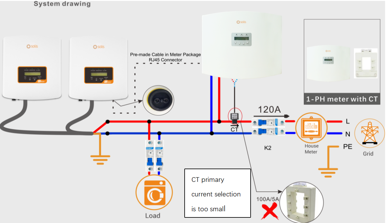
3.
The selected secondary current of the CT is not 5A. The Solis 5G series
EPM box requires a CT with a secondary current of 5A. If it is 200mA or
1A, inaccurate power detection of the grid may lead to issues with the
EPM.
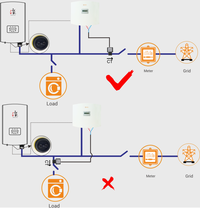
4. The CT installation position in relation to the EPM Box
is incorrect. If it is installed on the load branch circuit, abnormal
power control can occur. See the diagram below.
3) Why is the grid power shown by the EPM different to the meter reading?
Answer:
When this problem occurs, the following factors should be considered:
1. Check the CT current ratio setting of the EPM reflects the actual PV system specifications
Advantage setting→Set CT Ratio→Set Para:
2. Confirm whether the secondary current of the CT is 5A
3. Use
a clamp meter to measure the current at the CT and compare it with the
current displayed by the EPM-Information to determine whether the CT or
the EPM itself is faulty
4. Check whether the grid voltage displayed by the EPM-Information has an abnormal value
4) What does the “CT fail-safe” alarm mean?
Answer
This is usually caused by a connection failure between the CT and the EPM. The following action can be taken to troubleshoot:
CT
fail-safe means that the EPM box detects that the CT is not connected.
You should check the wiring between the CT and the EPM box or use the
current value of each phase of the EPM-Information to determine which CT
is causing the error message
2.Note: When this fault occurs, all
installed inverters will also display a "Failsafe" alarm message. If
this message does not appear it means that the inverter's "failsafe"
option is switched off.
5) "RS485 Fail" or "RS485 AllFail" alarm is displayed on the EPM box
Answer
“RS485 Fail”
This
indicates that the RS485 communication between the inverter and the EPM
Box in the entire system is faulty. You should check the connection
between each inverter and the RS485 bus;
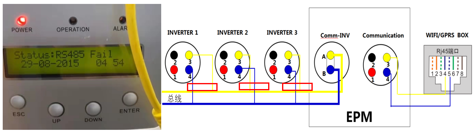
Use
a multi-meter to measure the voltage between the A pin and B pin of
each inverter's RS485 communication port which under normal operation
should read about 1.6V. If there is a large deviation from this, it
indicates that the inverter's communication terminal could be faulty.
You should also check whether the number of inverter settings on the EPM and the inverter's slave address settings are correct.
“RS485 ALLFail”
This indicates that the RS485 communication between all inverters and the EPM is faulty.
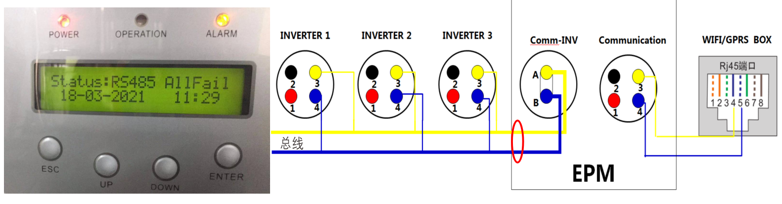
You should check the connection between the RS485 bus and the EPM by doing the following:
①
Unplug the RS485 bus connector and use a multimeter to measure the
voltage between the A pin and the B pin, which in normal state should
read about 1.6V. If there is a large deviation from this, the A pin and
B pin of the RS485 terminal on the inverter side may be reversed.
②
If there are intermittent "fail-safe" problems, it may be caused by
on-site interference. If this is the case, it is recommended that you
upgrade to a higher quality, shielded RS485 cable.


 中国
中国
 India
India
 Việt nam
 Australia
 대한민국
대한민국
 پاکستان
 ประเทศไทย
Filipino
 Malaysia
 Bangladesh
 Sri Lanka
 Indonesia
 Узбекистан
 Ireland
 Türkiye
 United Kingdom
 France
 Deutschland
 Nederland
 España
 Česká republika
 Sverige
 Polska
 Україна
 Italia
 Português
 България
 Magyarország
 Lietuva
 Ελλάδα
 United States
 Canada
 México
 Brasil
 República de Chile
 South Africa
 المملكة العربية السعودية
 الجمهورية اللبنانية
 امارات عربية متحدة
 اليمن
اليمن
 المملكة الأردنّيّة الهاشميّة
 جمهورية مصر العربية
 la République Tunisienne
 Tanzania
 Nigeria
 Other Countries and Regions